- Giỏ hàng chưa có sản phẩm
You’ve likely heard about the use of industrial CT scanning and may be wondering if adopting it is the right move for your growing manufacturing business. This article provides a look at the current state of product inspection, what CT scanning combined with analysis and visualization software brings to the table, and the benefits that moving to this more advanced methodology can provide.
Is your current inspection method seeing everything?

Whether it’s engine blocks or solder joints on printed circuit boards, manufacturers know that whatever they produce, they must also inspect. Vision and laser-based inspection systems, optical comparators, micrometers and various gauges – there’s a broad range of metrology and inspection equipment being used these days. But such tools may not be providing users with everything to know about a product because they can’t always reach, or even see, specific part features, let alone accurately identify defects within the material itself.
Some non-destructive testing (NDT) approaches (such as eddy current and magnetic particle inspection) can detect shallow material flaws. Destructive testing, through cross-sectioning of a workpiece, is both costly and limited. When the goal the is meeting the most exacting specifications for quality control that can be achieved, a better way is needed to peer deep inside parts and extract detailed, accurate data about every structure inside data that can then be used to asses dimensional conformity, analyze structural integrity, predict performance, and perhaps even guide changes to manufacturing methods.
An introduction to industrial CT scanning and its uses
The technology to achieve this level of quality control exists and it begins with industrial CT scanning. Also known as 3D-computed tomography, this technology works by processing multiple X-ray images to gain a dimensionally accurate 3D model of the object being scanned.
The wavelengths used with industrial CT scanning are both shorter and more energetic than those used to X-ray a broken bone, which means they can easily penetrate dense materials such as wood, plastic, composites, and metal. And where X-ray machines take a one-sided image of the target without depth resolution, industrial CT scanners view all sides of an object and use mathematical methods to reconstruct a volume. This resulting 3D volume offers an interior view that no other technology provides.
Yet CT scanning alone does not deliver everything needed to assure and document product quality. The best scans in the world won’t tell enough without the right software tools for analyzing and visualizing scan data.
Advanced analysis and visualization software, such as that provided by Volume Graphics, supplies supporting capabilities that far exceed the native image gathering potential of CT equipment alone: Automated collection and analysis of scan data, defect detection, measurement functions including GD&T, FEM meshing tools – these are just some of the available CT data-analysis software capabilities that enable users to fully streamline quality assurance activities and deliver high-quality, finished parts.
A quick look at how CT scanning and software work together
Regardless of how users choose to access the power of CT for quality assurance, it may be useful to have a brief review of the processes involved.
Key to the CT scan and the critical data analysis that follows is the voxel. When an X-ray beam’s high-energy photons pass through their target, some are absorbed and others scattered, but the remainder strike the detector screen opposite the X-ray source. They then energize the (two dimensional) pixels there in proportion to the density of the material being scanned as well as its thickness and attenuation values, and generate a series of grayscale images.
This is where the computational part of the process comes in. CT- data visualization software reconstructs those millions of pixels into three-dimensional voxels. Then, employing advanced mathematical algorithms, the software creates a full three-dimensional visualization of the exact object that’s been scanned. Next, a rainbow of tools can be employed to analyze the material density, stress patterns, internal defects, design flaws and a host of other attributes of what’s been scanned – which includes machined metal parts, 3D-printed prototypes, plastic injection-molded parts, fiber-reinforced plastics, or anything else that’s scannable.
These software-based analyses and visualizations can be highly valuable to manufacturers in almost any industry, allowing designers and engineers to understand failure modes, validate critical part features, predict how products will perform, and both quantify and qualify manufacturing processes. That’s the beauty of CT scanning when married to analysis and visualization software.
The cost/benefit justification for CT scanning and analysis
As an example, consider a plastic injection-molded connector, like the ones found in cars, refrigerators, or laptop computers. Manufacturers produce these surprisingly detailed and accurate objects via multi-cavity molds, each of which must be validated by carefully inspecting the parts that come out of them.
Measuring the products’ visible features is accomplished using one of the metrology tools mentioned earlier. The unseen interiors are a different story, however. To inspect these, manufacturers often have to destroy representative part samples. In this case, a technician must saw the connector into sections, polish the rough edges, and then inspect the now-visible faces. If a defect is found, the part must be made over again. As the mold cavity wears, the process must be repeated. After a shift change, or a new batch of resin, or an equipment malfunction, the repetition may continue.
The bottom line? The status-quo methodology of sectioning manufactured parts, whatever they are, is expensive, time-consuming, and error-prone. Consider all those connectors in between, the ones that weren’t destroyed: Unless the manufacturing process is perfectly stable, which is rarely the case, there’s always a question mark left hanging about the parts or part sections left unchecked.
While the question mark can be relatively small in the case of molded components and similar high-volume products, the same can’t be said about mission-critical, costly products such as turbine blades, engine blocks, high-end electromechanical assemblies, and the newest darlings of the manufacturing industry, 3D-printed parts. In such cases, major manufacturers worldwide have already set up in-house CT scanning facilities while others with more limited financial or bandwidth resources are turning to CT-scanning service providers.
How to use CT analysis to build better tools
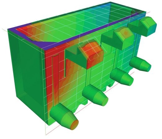
For a deeper understanding of how this methodology can help create better tooling, improve part quality, increase product lifespan, and reduce costs, let’s take another industrial example, this time metal casting. This is a mature and well-understood process, used for automotive powertrain components, pumps and valves, turbine blades, and practically anywhere robust, yet often complex, metal parts are needed.
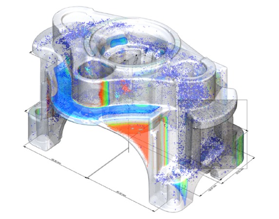
There’s just one problem (and it’s quite similar to that faced by plastic injection molders). Because the molten material used with casting and molding is made to flow through a series of cavities, the likelihood of air entrapment is high. As a result, voids and porosity are an all-too-common occurrence, and the only way to detect such flaws short of sectioning the part and thus destroying it is with high-end CT scan-data analysis and visualization software.
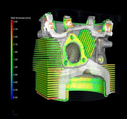
There’s more to it than finding a bunch of bubbles in a metal part: There’s also the critical aspect of shrinkage and warpage to consider, as well as wall thickness, inclusions (trapped foreign material), draft angles, as-cast to as-designed comparisons – never mind the need to measure and report dimensional information on hidden part details. These are just a few of the roles that industrial CT-data analysis and visualization software is now beginning to take on in casting houses everywhere.
Such information gives toolmakers the knowledge they need to make intelligent decisions about mold design. Since they now have a better handle on the unseen world, they can identify what steps should be taken to accommodate thermal effects and material flow within their tools.
Here again, a capable CT-scan-data analysis and visualization software package simplifies this process by generating meaningful views of the workpiece (and/or the tool itself). Manufacturing-geometry-correction tools within the software reduce the number of design iterations needed to obtain an optimized tool, and enable the export of values to the shop’s CAD/CAM software for use in the manufacturing process.
This scenario applies equally to forgings and stamped, bent, or formed metal parts; anywhere a machined tool is used to shape metal, CT-scan-data analysis can be used to make it better and less expensive to produce.
Other important industrial applications of CT scanning, analysis, and visualization
The CT-scanning, analysis and visualization process is fast, sensitive, reliable, non-contact and nondestructive. Its powerful capabilities for inspection and metrology provide knowledge far beyond traditional optics or tactile metrology. This advanced methodology can be applied at any stage of production, from prototyping to even testing in-line on the shop floor. The variety of potential applications for industrial CT-data analysis is broad and growing.

One of the newest fields in which CT is being applied is additive manufacturing, a.k.a. 3D printing. An ever-growing number of product designers, MRO suppliers, and entrepreneurs are taking advantage of this relative newcomer to the manufacturing industry for use with prototype and low- to mid-volume production of metal, polymer, and composite parts. But, as with cast and molded parts, concerns continue to exist over material integrity. This is why a large percentage of additively-manufactured parts, especially those made of metal or intended for flight-critical use, are inspected using CT scanning.
CT scanning, analysis and visualization isn’t limited to metals and polymer materials. Composites, used in a wide variety of industries to manufacture parts for wind-turbines, boats, helicopters, cars, other vehicle bodies and more can be analyzed in depth for fiber orientation, part delamination, undulations from process errors, and gluing integrity.
Examples of other uses
Hundreds of such applications exist, running the gamut from car-key fobs to industrial robots to rotor blades to carbon-fiber racing bikes. In each example, after scanning is done, CT-integrated software helps manufacturers analyze, visualize, measure, and document workpieces inside and out. The result is continuous product improvement, reduced engineering time and costs, and fewer failures in the field.
Time and cost argument for CT scanning, analysis, and visualization

As discussed earlier, destructive sectioning is clearly limited (and costly). Consider once more our injection-molded connector. You might get lucky and cut the part in two at precisely the right place to find an air bubble or void, but chances are just as likely that defects you can’t see will lie above or below the cutting plane. CT-data analysis and visualization software, on the other hand, allows the quality engineer to take a virtual flight through the entire part from any direction. Nothing remains hidden, no matter how tiny it might be.
Better yet, the right CT-data analysis and visualization software eliminates much of the tedium associated with such part exploration. It supports high-quality renderings and exploded views of parts and assemblies. It makes possible the analyses of cracks, porosity, cellular structures, and fiber alignment, edge detection and surface determination, unrolling or flattening of cylindrical objects and more. Inspection plans are easily generated and executed, part features and geometries measured, potential design or manufacturing failures identified.
The software also automates much of this work, with integrated engineering workflows and other tools to streamline the analysis processes, making the often-huge data sets from CT scanning easier to manage, merge, and analyze.
Industrial CT-scan data analysis and visualization software can make what would otherwise be a highly complex process perfectly suitable and valuable to business profitability whether used on the factory floor, by a metrology service provider, or integrated with the research laboratory of a university.
Maximizing return on industrial CT scanning
CT scanning has evolved into a mainstream process. When equipped with capable software, automakers can leverage the largest scanning machines to image complete vehicles for design analyses, while 3D-printing service bureaus and equipment manufacturers can use smaller, less-expensive machines to validate material integrity or measure internal part features. Sitting between these two extremes are those who produce wooden furniture, foam insulation, metal castings, plastic bottle caps, and everything else imaginable. Infact any manufacturer that wants to know what exactly is happening inside their products.
And thanks to the industrial CT-scanning industry’s overwhelming adoption of advanced software they can see, and understand, precisely what is going on. The leading CT software company, with 80% market-share, offers solutions to fit every industrial need, from material and geometry analyses to volume meshing, structural mechanics, simulation and more. All are available as easy-to-use modules that offer highly accurate, full-breadth analysis capabilities, giving manufacturers every tool needed to improve their products, no matter what they’re making.
Simply put, industrial CT scanning eliminates doubt. There are no question marks left hanging over any scanned part following analysis with the advanced software tools available. Aside from the cost and efficiency benefits made possible by this increasingly essential, advanced technology, industrial CT scanning also reduces risk – so product certification is assured, enhancing corporate reputation.
Whatever it is you’re manufacturing, industrial CT scanning, when combined with data analysis and visualization provides the final word on quality assurance and delivery of competitive products whatever the target marketplace.
Bài viết liên quan
Tin mới nhất